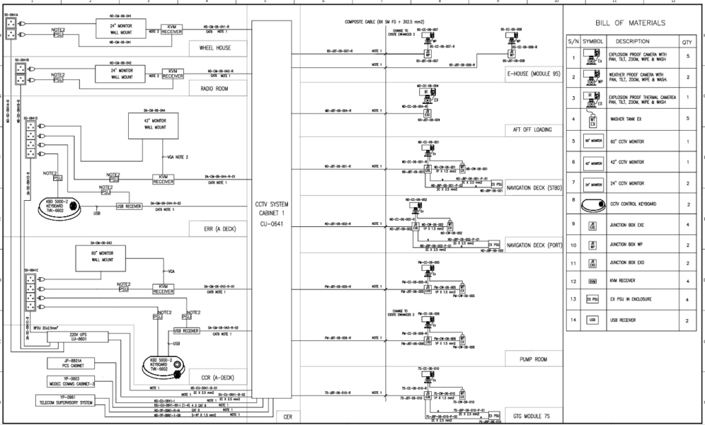
The Typical Block Diagram for a CCTV system on board FPSO Vessel
Location: Installed in various hazardous and non-hazardous areas such as the deck, engine room, living quarters, and topside process areas.
Types: Fixed cameras, PTZ (Pan-Tilt-Zoom) cameras, thermal cameras (for night vision or low visibility areas), and specialty cameras (e.g., for flare stack monitoring).
Explosion-Proof: To meet offshore safety standards (ATEX, IECEx) for hazardous zones.
2. Camera Enclosures
Material: Stainless steel, ensuring corrosion resistance.
Certifications: Designed to prevent ignition sources in hazardous areas.
3. Camera Power Supply Units (PSU)
Function: Provides power to the cameras, typically through Power over Ethernet (PoE) or separate power supplies.
Redundancy: Often integrated with UPS (Uninterruptible Power Supply) for critical operation.
4. Network Switches (Ethernet Switches)
Location: Distributed in control rooms or communication cabinets across the FPSO.
Function: Switches aggregate camera data for transmission to the control center. In some cases, they are PoE switches that power the cameras.
Industrial-Grade: Designed to withstand harsh marine environments (humidity, vibration, and temperature).
5. Fiber Optic Backbone
Purpose: High-speed data transmission from remote locations on the vessel to the central control room.
Advantages: Fiber optics ensure data integrity and long-distance transmission without signal degradation.
6. Network Video Recorder (NVR)
Function: Receives video streams from the cameras over the IP network and records them for storage and future playback.
Storage: High-capacity storage drives, with RAID configurations for redundancy.
Playback/Export: Allows operators to review footage or export data for investigations.
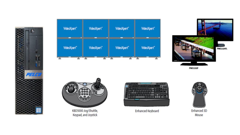
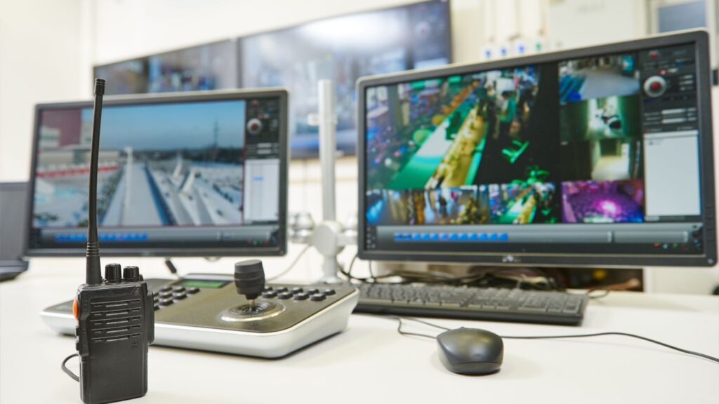
7. Control Room / Monitoring Station
Main Component: Central station where operators monitor live video feeds and recorded footage.
Monitors: Multi-screen setups for viewing several camera feeds simultaneously.
Video Management Software (VMS): Used to control camera functions like PTZ, video recording, and analysis. It also provides features like motion detection, alarms, and event logging.
Redundant Systems: Backup servers and data centers for continuous operation in case of hardware failure.
8. Explosion-Proof Joystick Controllers (for PTZ cameras)
Purpose: Allows operators to control the movement of PTZ cameras remotely for detailed area inspection.
9. Satellite / Remote Communication (Optional)
Purpose: Enables remote viewing and control from an onshore control center through satellite or radio links. This is often used for remote support and monitoring from a distant operations center.
10. Alarm Integration
Integration: The CCTV system is often integrated with the FPSO’s overall safety systems, such as PAGA (Public Address and General Alarm) systems, fire detection, and access control systems.
Event Triggers: Cameras are programmed to record or alert when alarms are triggered by other systems.
Get the Right Team
With over 10 years of experience in the FPSO industry, Team Vivo Asia is experienced and skilled in the design, drawings and commissioning of CCTV systems. Enquire today to discuss your requirements!